Definitions
Dataset Section
Relationships
Relationships were defined earlier in this user guide.
See Relationships.
Conversion Records
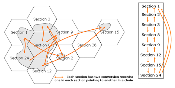
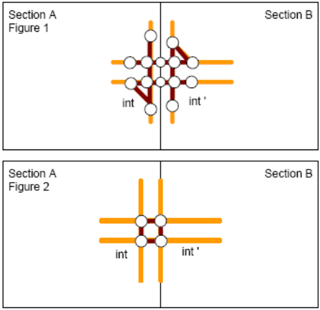
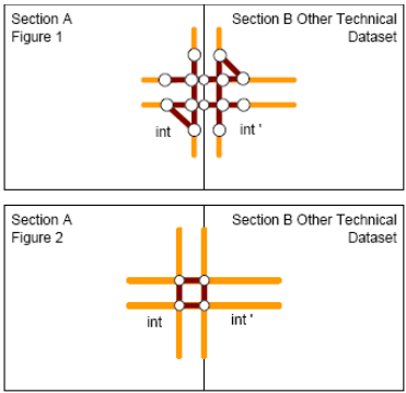
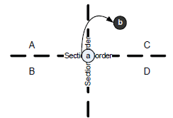
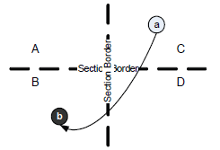
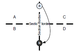
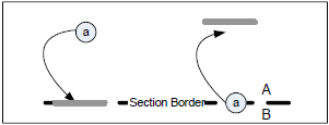
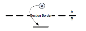
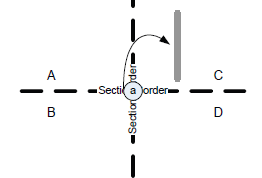
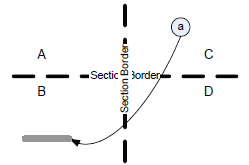
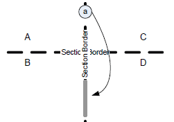
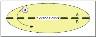
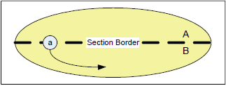
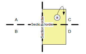
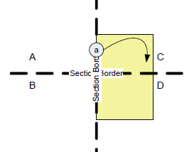
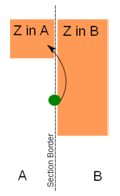
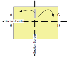
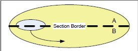
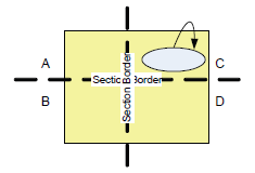
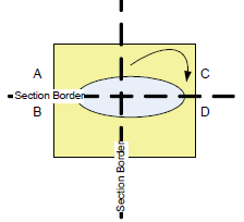
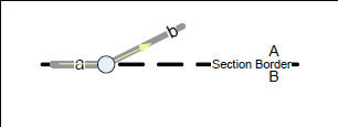
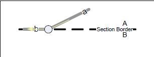
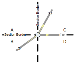
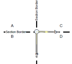
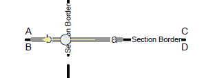
For features that are section-crossing (GDF-AS) or technical dataset-crossing (GDF-AR, Shapefile), conversion records are created to provide a relation between the local and the foreign feature ID.
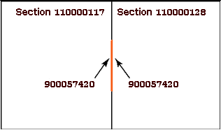
Conversion records are delivered as either separate records (GDF-AS: record 46) or as separate files (GDF-AR: CN1-CN4; Shapefile: CN) to enable dataset crossing linking of Features. They contain the ID of a feature in the current dataset together with the ID of the same feature in the neighboring dataset.
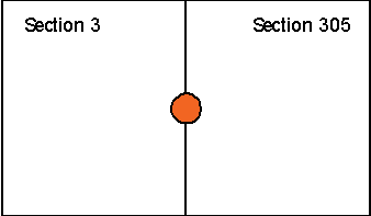
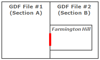
The dataset identifier of the foreign dataset differs from the internal dataset identifier when adjacent sections belong to different countries.
Example: Internal dataset is Spain (country code 724) and the foreign dataset is Portugal (country code 620) then the dataset IDs in each dataset differs.
Example: For technical datasets that belong to one country, the dataset IDs are the same.
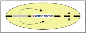
The section identifiers of the foreign dataset always differ from the section identifier of the internal dataset.
| POINT | LINE | AREA | COMPLEX |
|---|---|---|---|
| Administrative Boundary Junction | |||
| Brunnel | |||
| Center Point of Feature | |||
| City Center | |||
| Junction | |||
| Railway Element Junction | |||
| Water Center Line Junction | |||
| Adress Area Boundary Element | |||
| Brunnel | |||
| Ferry Connection | |||
| Railway Element | |||
| Road Element | |||
| Water Center Line | |||
| Water Element | |||
| Index Area | |||
| Urban Agglomeration | |||
| Intersection | |||
| Road | |||
| TMC Location | |||
| TMC Path |
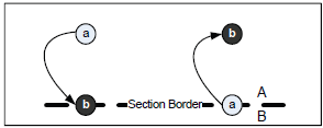
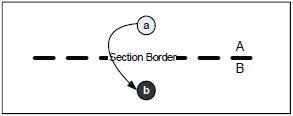
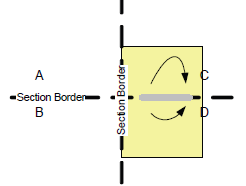
IMPORTANT:
Figure: Chaining Section IDs