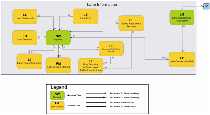
1. The first table to check when dealing with lanes is the nw table.
nw Data Example:
Table 1.
| ID |
LANES |
| 108400000197899 |
4 |
Explanation: The LANES field tells you if and how many lanes are present on a road
element.
2. The ll table gives information on what type of road divider line is used to
separate the lanes (e.g., Interrupted Line with Long Lines, Double Solid Line).
ll Data Example:
Table 2.
| ID |
SEQNR |
DIVIDERTYP |
VALIDITY |
| 108400000197899 |
1 |
2 |
R010 |
Explanation: In order to use this information:
- Search the road element ID in the ID field and then the sequence number (in the SEQNR
field) to see if there could be more than one line for the record.
- See the DIVIDERTYP field which describes what kind of divider line is present. For
example, a value of "2" indicates that the line is a Double Solid Line. For a list of
all possible values, see the MultiNet® Shapefile Format Specifications
document.
- Finally, the VALIDITY field identifies which lane the line is present in. For example,
value "R010" means that, reading right to left, the second lane is the lane that the
information is valid for. Line direction is defined according to the map digitalization,
so it must be checked using the start junction (F_JNCTID) and end junction (T_JNCTID)
IDs in the nw table.
3. The ld table gives information about the type of arrows (indicating lane
direction that the arrows point to) that are on the lane.
ld Data Example:
Table 3.
| ID |
SEQNR |
DIRECTION |
VALIDITY |
| 108400000197899 |
1 |
3 |
R010 |
Explanation: In order to use this information:
- Search the road element ID in the ID field, and then the field sequence number (in the
SEQNR field) to see if there could be more than one line for that record.
- See the DIRECTION field to find what kind of arrow is present on the road surface. See
the ld table in the MultiNet® Shapefile Format Specification
document for a complete list of numeric values.
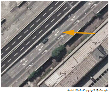
- The DIRECTION numeric values can be combined to best represent how the arrows look.
For example, "1" = straight, and "2" = slight right. The sum of the two would make a
value of "3" = there is an arrow depicting straight and an arrow depicting a slight
right. See the photo below for an example.
Figure: Example of the DIRECTION field = "3" in the ld Table
4. The ln and lp tables give information when connectivity between lanes is
necessary. This occurs when there is a change of lane when crossing road elements (e.g., you
are in lane 2 on the first road element, and end up in lane 1 of the second road element
after the crossing). Connectivity is present only when there is a change of lane and only
when this happens in the real world, not when the change of lane is due to opposite
digitalization direction. In order to use the information, start from the ln table which is
related to junctions (nodes).
ln Data Example:
Table 4.
| ID |
FEATTYP |
FROMTO |
JNCTID |
| 108400100201661 |
9860 |
1/1 |
108400200101251 |
| 108400100201661 |
9860 |
1/2 |
108400200101251 |
| 108400100201661 |
9860 |
2/3 |
108400200101251 |
Explanation: The ln table tells you:
- at the junction ID (JNCTID), a lane connection is present;
- the feature type (FEATTYP) is Relationship 9860 = Lane Connectivity;
- which lanes are involved from the values in the FROMTO field. For example, a value 1/2
means that you are on lane 1 in the starting road element and you end up in lane 2 in
the destination road element (lane 1 and 2 are always defined according to
digitalization direction starting from the right).
5. Once you have the connectivity ID and the lanes involved, you can now search for the
same ID in the lp table to tell you which road elements are involved.
lp Data Example:
Table 5.
| ID |
SEQNR |
TRPELID |
TRPETYP |
| 108400100201661 |
1 |
108400000369141 |
4110 |
| 108400100201661 |
2 |
108400000062923 |
4110 |
Explanation: The first sequence number (SEQNR field) is the starting road element
and the second is the destination road element. The IDs of starting and destination IDs are
in the TRPELID field.
Note: Only the starting and destination road elements are present, not
any road elements that may lie in between.
6. Table lf table gives you information on the traffic direction allowed for each
lane.
lf Data Example:
| ID |
SEQNR |
DFLANE |
VT |
VALIDITY |
| 108400000369141 |
1 |
3 |
0 |
R11 |
Explanation:
- The sequence number (in the SEQNR field) indicates if there is more than one line for
the record.
- The DFLANE field indicates the direction of traffic flow for the lane. In this
example, "3" = Closed in the Negative Direction.
- VT indicates vehicle type. In this example, "0" = All vehicles.
- VALIDITY indicates the valid lanes for this information. As in the VALIDITY fields of
the other Lane files, lanes are read from right to left.