Routing with MultiNet® Shapefile

Several Transportation Element Attributes are useful for assigning weight in routing calculations, depending on what kind of routing options are important.
ROUTING OPTION RELEVANT ATTRIBUTES FILE IDENTIFIER DESCRIPTION OF ROUTING OPTION
Shortest Route Feature Length (METERS) nw Shortest routes are based on distance only.
Fastest Route Average Speed Limit (KPH) See Average Speeds and Speed Restrictions below nw Fastest Route calculations are adjusted for optimal routing, realistic travel times and guidance toward a higher Transportation Network level without discarding Elements with a high connectivity function (having a high Functional Road Class.
Travel Time (MINUTES) nw
Network Class (NETCLASS); (NETBCLASS); (NET2CLASS) nw
Speed Restriction Type (SPEEDTYP) See Average Speeds and Speed Restrictions below sr Speed Restrictions can be the maximum speed, recommended speed or lane dependent.
Conditional Route Form of Way (FOW) nw Conditional routes are created to avoid unwanted situations and conditions while travelling, including:
  • Road types (FOW1, Motorway, FOW14, Pedestrian Zone);
  • Bad roads (RDCOND);
  • Expensive roads (TOLLRD);
  • Roads not totally captured and not conforming to TomTom® specifications, or roads not suited for motorized traffic (BACKRD), (STUBBLE).
    Note: Note: A Back Road is a rural road not optimal for travel.
  • A road charge needs to be paid in order to use the roads (CHARGE). This differs from a toll as it is a one-time payment during a specified time span.
Freeway (FREEWAY) nw
Road Condition (RDCOND) nw
Toll Road (TOLLRD) nw
Back Road (BACKRD) nw
Stubble (STUBBLE) nw
Charge to be paid (CHARGE) nw

Average Speeds and Speed Restrictions

The KPH field in the Shapefile Network file (nw) represents the average speed over the entire distance of a road. This calculation is based on the Functional Road Class (FRC), Form of Way (FOW) and whether the Road Elements travel through Built Up Areas (BUAs).

The SPEED field in the Shapefile Speed Restriction file (sr) represents either the maximum, recommended or lane-dependent speed for a single Road Element. The speed type is identified in the SPEEDTYP field.

Note that a particular Road Element can be flagged in the nw file with an average speed that may be higher than the sr maximum speed value.

The VERIFIED field in the Shapefile Speed Restriction file (sr) indicates whether the speed values were verified by reliable sources or were calculated (Not Verified).

Restrictions and Maneuvers

Restrictions and Maneuvers are limitations to take into consideration when calculating a route.

Restrictions

A Restriction limits access to part or all of a Transportation Element.
RESTRICTION TYPE TABLE ATTRIBUTE COMMENTS
Digital Direction of a Transportation Element nw, rs Direction of traffic flow (ONEWAY)/ (RESTRTYP = DF) Direction depends on the relative positions of the F_JNCTID and T_JNCTID of an Element.
Access to the F_JNCTID and T_JNCTID nw, rs Blocked passage at start or end of junction (F_BP; T_BP)/ (RESTRTYP = BP) A physical obstruction to prevent vehicle access (e.g., to a Campground, School).
nw, rs Private Road (PRIVATERD) Road not open to public motorized vehicles.
nw, rs Construction Status (CONSTATUS)/ (RESTRTYP = 6Z) Road closed for construction/maintenance.
Time Restriction td Time Domain (TIMEDOM) Closed for a measurable amount of time.
Vehicle Type rs Vehicle type restriction (VT) The type of vehicle restricted.
Special Restrictions rs RESTRTYP = SR Special restrictions include roads accessible by employees only, residents only, authorized personnel only, etc.

Blocked Passages

According to the MultiNet data specification, a “Blocked Passage is the database representation of a physical obstruction located on a road.” There are Blocked Passage attributes in Composite Blocked Passages (BPAS) that are applied to more precisely define the blocked passage.
  • Vehicle Type (VT) Restriction - Defines the type of vehicle that the blocked passage applies to;
  • • Validity Period (VP) Restriction - Defines the time period that the block passage is valid.
Therefore, a road element can have a Blocked Passage (BP) but have vehicle type (VT) or validity period (VP) attributes applied that will allow passage at certain times and / or for certain vehicles.

Removable Blockage

Removable Blockage is another attribute that can be applied to a road element in cases where TomTom can capture the method of bypassing the blockage (e.g., keyed access, guard controlled or accessible by emergency vehicles). If a road element does not have the removable blockage attribute, the blockage still may be bypassed due to the vehicle type or the validity period of the blockage as mentioned above.

Maneuvers and Routing

A Maneuver represents a mandatory, preferred or prohibited access of a Transportation Element, in relation to another Transportation Element.

See Maneuvers (mn) earlier in this user guide for descriptions.

The Elements that comprise a Maneuver Relationship are listed in the Maneuver Path Index table (mp). Each Element has a Sequential Number (SEQNR) as listed in the following table:
SEQNR FEATURE FUNCTION RELATES TO
1 Transportation Element (Road or Ferry Element) Element travelled on before arriving at a traffic sign indicating a maneuver. ID in the nw table
2 Junction Location of a traffic sign, where the maneuver actually begins. This is also the central reference point or anchor point to build a Maneuver Path (identified by its own ID). JNCTID in the mn table; F_JNCT / T_JNCT in the nw table
3 Transportation Element Element that is routed to, and for which the maneuver is valid coming from the first Element. ID in the nw table
4 Transportation Element Element for which the maneuver is valid, coming from the preceding Element (e.g., 3). ID in the nw table
All necessary information to describe simple maneuvers may only require the sequence of two features or three features. See example below.
Example: Prohibited Maneuver of type Implicit Turn between two Road Elements

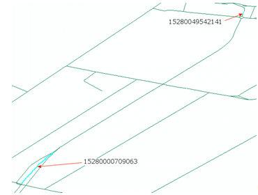
Figure: Implicit Turn Maneuver in Map Display

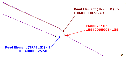
Figure: Implicit Turn in Tables

Interpretation:
Maneuver ID 108400600014158 defines the maneuver decision point between two Road Elements. The Maneuver Path Table provides information defining the sequence of the maneuver:
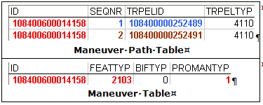
    • The first Road Element (4110) in the maneuver path is 108400000252489.
    • The second Road Element (4110) in the maneuver path is 108400000252491.

      The Maneuver Table provides information defining the type of maneuver:

    • The feature type (FEATTYP) 2103 = Prohibited Maneuver.
    • The Prohibited Maneuver type (PROMANTYP) 1 = Implicit Turn.

Partition-Crossing Maneuvers

Partition-crossing Maneuvers are Maneuvers where the Junctions are lying on a partition border. The Elements that are present within a partition are included in a Maneuver Relationship. The Sequential Number (SEQNR) Attribute contains the exact position that an Element occupies in a Maneuver Relationship chain. The Elements of the Maneuver located in the adjacent partition are represented by a Dummy Feature (and as such a Dummy ID: the neighboring feature's ID).
Note: All Maneuver parts lying on a partition border and all Maneuver Dummy Features are listed in the Conversion Records stored in the cn table.

Signage Information

Signpost information is useful for directional and destination information. Transportation Elements that lead to a destination indicated by a signpost can be linked. Route Numbers also play an important role in routing.

Traffic Signs allow for messages such as lane-dependent speed restrictions, or warnings for traffic jams.

Signposts

Signpost information, near a road, contains a directional component and a destination component.
  • Directional information includes the Relationship between the Road Element ("from where") that leads to the intersection the signpost refers to, and the first Road Element ("to where") leading from the intersection to the destination. A signpost can indicate a direction by a pointing shape of the signpost or by arrows.
  • Destination information can include text, route number, exit number and a pictogram.
Direction and destination information are present in MultiNet® Shapefile in different tables. The different signpost-related tables are linked by means of a Signpost ID.

SP (Signpost Path Index) Table

The sp table describes the path of a Signpost. The first Transportation Element is the start of the path; the second Element is the Junction of the Traffic Sign location; and the last Element is the end of the path.

SG (Signpost) Table

The sg table includes the Junction Attribute and a link to the color palette that is used to identify the appropriate sign colors for Administrative Areas a0 and a1. The aoas and a0av Composite extra attribute files contain contain the information necessary to build the proper colors for sign text, background color and border color.

SI (Signpost Information) Table

The si table includes the text and pictogram descriptions. If a signpost has multiple textual descriptions (for example, when the same destination is described in two languages), or multiple pictograms (for example, Railway Station with Parking Facility on the same signpost), then the records are repeated in the si table for each textual description or pictogram, and ordered by a Textual Context Sequential Number (SEQNR).

When a textual description has more than one pictogram or destination, the pictograms or destinations are listed as they occur on the signpost with respect to the text: the signpost is treated as an information matrix. The si table includes the DESTSEQ (Sequence in the Destination Set) field to determine the line in this matrix. If Route Numbers are listed on the signpost in one line, the sequence within the line is determined in the RNPART field (Route Number Part).

Both text and pictograms are stored in the TXTCONT field of the si table.

Example: "Waterloo Station // 13 // 11" indicates that a sign has, reading left to right, the name of the station, then a Railway Station pictogram, then a Parking Facility pictogram. "13 // Waterloo Station // 11" indicates that the Railway Station pictogram is to the left of the station name on the signpost.

The si table also indicates the type of connection information that the signpost represents (CONTYP field).

The AMBIG field indicates whether the destination information is ambiguous or clear.

Route Numbers

Route numbers are defined according to national or international standards that vary from country to country. A Transportation Element can belong to more than one system, and thus have more than one route number.

Route Numbers that appear on route shields are stored in the rn table's SHIELDNUM field. The route type is stored in the RTETYP field of the rn table. See Route Number Types earlier in this user guide.

Some route numbers indicate which direction they lead to. This is stored in the Route Directional field (RTEDIR). Together with this directional, the Directional Validity Direction (relative to the digitizing direction) is stored in the RTEDIRVD field.

The hierarchy of the route numbers for a particular country is stored in the PRIORITY field.
Note: The nw table also has a ROUTENUM field: this stores only the primary route numbers, i.e., the Route Numbers with the highest priority (according to the standards of a particular country).
Note: Certain route numbers indicate that a road is part of a tourist route. Road Elements that are part of such a route have an entry in the to (Tourist Roads) table.

Traffic Signs

Traffic Signs are a type of signpost that can hold different types of information. This can range from lane-dependent speed restrictions at certain periods (e.g., during rush hour, construction work) to warnings such as "Tunnel/Mountain Pass Closed" or "Traffic information on FM107.6."

In MultiNet® Shapefile format, traffic sign information is stored in two tables: ts and tt:
  • Traffic sign features are stored with their own geometry in the ts table.
  • The relation with the Transportation Element it belongs to, the direction in which it is valid and the location on that Transportation Element are stored in the tt table.

TMCs

The Traffic Message Channel (TMC) is a system of collecting, coding and broadcasting trafficrelated information. Traffic announcements are transmitted as a coded message by a Radio Data System (RDS). The coding of the information is assembled according to a uniform global standard and is independent of language. The message is always in the same format:
  • there is an incident caused by something;
  • on a specific road;
  • in a specific direction;
  • and between two locations.
The TMC system process generally follows these steps:
  • The traffic information is collected by the Traffic Information Center (TIC) and sent to the Data Service Provider.
  • The Data Service Provider checks the quality of the information and generates the coded messages. The coding of the information is done according to a uniform global standard. These messages are language independent.
  • The Data Service Provider sends the coded messages to the Broadcaster for transmission to the receiver as an RDS signal.

TMC Location Database

This database contains an official list of point, line and area TMC locations. A Point Location (event) is connected by means of Line Locations (roads connected as paths) within an Area Location. These Databases are subject to regular changes; therefore, MultiNet® Shapefile stores a reference to the TMC source table and the TMC table's version in the attributes TMCTAB and TMCLSTVER in the tp table (TMC Path).

Although TMC Location Databases list Point locations, Line locations and Area locations, TomTom® only captures Point Locations.

TMC Locations in MultiNet Data

A TMC Point Location is linked logically to a Junction, an Intermediate Point or another Landmark Point (e.g., Freeway Intersection). Therefore, TMC Point Locations are not always Level 1 point features.

To link a Point Location with its database representation, TomTom introduced the TMC Locations.

A TMC Location is related to one Point Location in the TMC location database and refers to objects along or at the Road Network.

TMC Location Structure

Each TMC Location has a TMC Location Reference Code (according to the ALERT C protocol). This code is composed as follows (ABBCCCCC):
  • A = EBU (European Broadcasting Union) Country Code (hexadecimal);
  • BB = the number of the Location Database that is used;
  • CCCCC = Location Code (0-filled if fewer than five digits) in the Location Database.

TMC Location Structure in MultiNet Shapefile Data

TMC Location References in the TomTom® MultiNet® database are stored in two different ways:
  • As a Complex Feature (Feature Code 9020). These are stored in the tl table's TMCLOCREF field, which stores the TMC Location Reference Code (ABBCCCCC) as defined above. The Transportation Elements and Junctions composing this Complex Feature are indexed in the tc table.
  • As a Level 1 RD attribute of a Road or Ferry Element. This attribute can be retrieved from the rd table's RDSTMC field. This field stores the TMC Location Reference Code as "ABCCDEEEEE." Where:
    • A = Direction of Road Element (from start Junction to end Junction) compared with the TMC chain direction:
      • + = in positive direction and external to the TMC point location;
      • - = in negative direction and external to the TMC point location;
    • B = EBU (European Broadcasting Union) Country Code;
    • CC = TMC Location Code;
    • D = TMC Direction of the Chain;
      • + = in positive direction and external to the TMC point location;
      • - = in negative direction and external to the TMC point location;
      • P = in positive direction and internal to the TMC point location;
      • N = in negative direction and internal to the TMC point location.
    • EEEEE = TMC Point Location Code (found in the official TMC location Databases).
Example: TMC Location Reference Code in the Shapefile rd table:
ID RDSTMC TMCPATHID
15280000693470 +817-45896 15280801601246

TMC Paths

A TMC Path is defined by the chain of TMC Locations using the positive or negative offset in one direction of the traffic flow. A TMC Path:
  • starts where a TMC Location does not refer to a previous TMC Location (no negative offset in the Location table);
  • ends where a TMC Location does not refer to a next TMC Location (no positive offset in the Location table).

TMC Paths in MultiNet Shapefile Data

TMC Paths are stored in the Shapefile tp table.

Example: The TMC Path data in the tp table:
ID FEATTYP TMCINFO TMCTAB TMCLSTVER
15280801601246 9021 45880/45904/- 817 9.1
  • Note that the ID in this table represents the referenced TMC Path ID in the above example.
  • TMCINFO data identifies the start TMC Location code (45880), end TMC Location code (45904), and the path direction (from end to start (-)).
  • The TMC location table is 817; the table version is 9.1.

Linking the TMC Path to the Network Geometry

The TMC Path Index table (tg) links the TMC path to the transportation element IDs located in the Network (nw) geometry. The transportation element IDs in the tg table are in the TRPELID fields.

Example: The TMC Path Index data in the tg table:
ID SEQNR TRPELID TRPELTYP
15280801601246 1 15280049542141 4110
15280801601246 2 15280049542149 4110
15280801601246 3 15280049542148 4110
15280801601246 4 15280049542144 4110
15280801601246 5 15280002596101 4110
15280801601246 6 15280002596133 4110
15280801601246 7 15280002596135 4110
15280801601246 8 15280002796808 4110
15280801601246 9 15280000709077 4110
15280801601246 10 15280000709063 4110
See the figure below for a map display of the first and tenth road element in the above path.

Figure: Location of the 1st and 10th Transportation Elements in the 15280801601246 TMC Path

Two TMC Location Codes in One Area

More than one TMC Location can refer to the same real-world object. In such a case the object is part of different Line Locations.

The following drawing illustrates two TMC location codes located at the same geographical latitude/longitude point. The 8000 Location Code is at the end of a TMC path that began on the vertical roadway. The 4311 Location Code is in a TMC path that runs on the horizontal roadway. The previous Location code in the path is 4310 and the next Location code in the path is 4313.

Figure: Two TMC Location Codes in One Area

Note: Codes used in the above example are for demonstration purposes only and may not reflect actual codes in your geographic area.

Summary of TMC Location and Path Information in MultiNet Shapefile Data

TMC Location information and TMC Path information are present in different tables in MultiNet® Shapefile.

tc (TMC Location Index) and tg (TMC Path Index) tables

The Index tables include a list of all Transportation Elements belonging to the same TMC Location or Path. A TMC Location also can include Junctions.

tl (TMC Location) and tp (TMC Path) tables

The tl and tp tables contain a link to the actual location references in the specific TMC database of some country. The bounding TMC Location References of a Path, in the tp table, are also in the tl table.

Figure: TMC Data Model

See additional descriptions of all TMC files beginning with TMC Information Along Road Elements (rd) in the Shapefile Format section of this user guide.