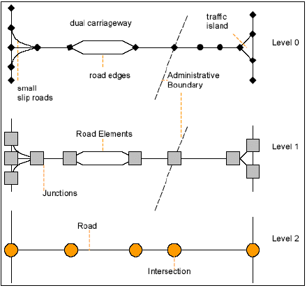
Understanding MultiNet |
A Feature is the GDF representation of a real-world object. All represented objects are related to the road environment. The road environment, however, covers a large field of topics.
A Feature Theme is a compilation of Features that share a common property.
Feature Class Name: A Feature or Feature Theme has a name that is derived from a term commonly used in everyday life.
Feature Class Code: GDF refers to a Feature or Feature Theme by a numeric code rather than by name. A code list (allcodes) database is included in your MultiNet delivery.
In MultiNet® Shapefile format, Level 0 is not present or available explicitly, but is part of the internal (invisible) structure of the Shapefile format.
Level 1 objects (also called simple features) form integrated systems, such as a road network or a land use area. Topologically related nodes and edges form higher objects in a mathematical or logical network, with information about the connectivity between them.
Level 2 objects (also called Complex Features) do not directly contain any geographic topology. Complex Features are present whenever a feature is built of several lower-level features.
Figure: Feature Levels 0, 1 and 2
All higher-level Administrative features (i.e., lower Administrative Order number) are complex (Level 2) features because they consist of various lower-level features. Sub-municipality settlements (Order 9) or municipalities (Order 8) are Area features that are grouped into higher-level Administrative features.
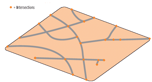
As with Administrative Area Complex Features, Roads consist of various lower-level features. In addition to objects associated with lower-level geometry, an Intersection is also an example of a Level 2 object. The topology associated with an intersection is contained in the Level 1 geometry of the roads and junctions that make up the intersection. Level 2 roads form a more generalized representation of the Road Network. Following are two figures: The first represents the lower-level components necessary to form Roads (Level 2) and intersections, and the second is a conceptual view of a Level 2 Road network.
See also How to Use Roads (Level 2) in the How to Use MultiNet® Shapefile and OSL section of this user guide.
Figure: Level 2 Roads - Components
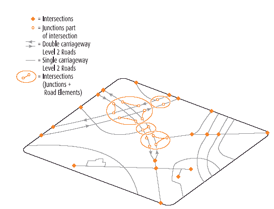
Figure: Level 2 Roads - Conceptual
GDF-AS field name (in documentation) = Feat_Cat
GDF-AR field name (in documentation) = FeatCat
Feature Category | Code | Notes |
---|---|---|
Absent Part | 0 | GDF-AR only |
Point Feature | 1 | |
Line Feature | 2 | |
Area Feature | 3 | |
Complex Feature | 4 | |
Relationship | 5 | Used in Relationship Records |
As an introduction to some of MultiNet®'s features, some general descriptions applicable to all formats are listed below in alphabetical order. This is only a partial list.
Administrative units are constructed topologically and hierarchically in the MultiNet® database, according to the GDF model. Complex Administrative Features consist of lowerlevel complex Features or simple Area Features (also see Level 2 earlier in this user guide). There are no overlaps or gaps between neighboring polygons, regardless of the administrative level.
At least 10 levels of Administrative Orders are defined for each country. The highest level, Order 0, is always the Country, which is made up of all lower-level units. Order 8 is also always present. The name of this level and the extension of its units are country-dependent. Order 8 is the lowest level that covers the whole territory of the country. It is especially important because many Relations between Features and the Order 8 Administrative Areas are made in the TomTom® database.
An Administrative Place is an administrative area that does not fit into a hierarchical structure. This subdivision may lie in more than one Administrative Area.
In Ireland, Administrative Place T is captured for each Townland and Administrative Place P is captured for each Postal Town as defined in the Geodirectory source of the Republic of Ireland.
In the U.S., Administrative Places are captured for each city represented in the latest Census Bureau TIGER® data.
A Built-up Area is an Area Feature independent from the Administrative Area structure. An Administrative Area can contain more than one Built-Up Area. A Built-Up Area corresponds to an area inside an Order 8 Area. An exception to this case is when an adjacent Order 8 Area does not contain a Center of Settlement. Then, the Built-up Area may cross an Order 8 Area.
Built-up Areas are determined geographically as a concentration of homes and buildings, mainly with a residential function. They improve map display and map readability.
The lack of an administrative value of a Built-up Area has implications for routing. The point where an urban speed limit applies does not always coincide with a Built-up Area boundary. If a Built-up Area is used for assigning travel-time weight factors to the Road Elements running through it, the assignment may produce only an estimation of the travel time.
IMPORTANT! As evidenced by the conditions above and the examples below, how an Index Area is built is directly related to how Administrative Areas, Postal Districts and other addressing and naming components are defined by individual countries and how that information is captured and stored in MultiNet® data.
Example: La Défense in Paris is an added value for address selection to the Administrative Order 8 Areas.
Example: The Index Area Order 8 of Brussels replaces the Administrative Area Order 8 of Brussels as this larger Area corresponds to the public perception of Brussels.
Land Cover | Land Use |
---|---|
In the real world, a Land Cover area does not necessarily have a clear extent or a definite boundary. In the digital map, therefore, the boundary may be arbitrary. | A Land Use area has a definite boundary. |
Land Cover areas are exclusive. A face cannot belong to more than one Land Cover Feature. For example, a Woodland cannot simultaneously also be Moor/Heathland. | Land Use areas are not exclusive. A unit of Land Use can coincide with
another unit of Land Use or with a unit of Land Cover. Example: An Industrial Harbor can be part of an Industrial Area. |
Land Cover Features are not section-crossing. | Land Use Features may be section-crossing. |
Exclaves (disconnected parts) are not allowed. Each Feature of Land Cover is composed of adjacent polygons within one section. | Exclaves are allowed. One single Feature of this category may be composed of several exclaves. |
For suggestions on the order of displaying Land Cover and Land Use features when programming for map display, see Displaying Land Cover and Land Use Areas later in this user guide.
Also included in the MultiNet Points of Interest Specifications document are many more POI categories and POIs only found in the MultiNet POI enhancement product.
A Point of Interest (POI), also called a “Service,” is a point representation of an activity at a specific location. “Service” represents the activity and not necessarily the building in which the activity takes place. Although the point also may serve as a destination landmark, the point does not necessarily represent an entire physical object.
Figure: Entry Point for a POI
Figure: Airline Access Entry Points to Airport POI
The Traffic Message Channel (TMC) is a system of collecting, coding and broadcasting trafficrelated information. Traffic announcements are broadcast as a coded message by a Radio Data System (RDS). The coding of the information is assembled according to a uniform global standard and is independent of language. The message is always in the same format: “there is an incident caused by something on a specific road, in a specific direction, and between two locations.”
The TMC system identifies the incident location by identifying pre-determined TMC points. A Point Location is connected by means of Line Locations (roads connected as paths) within an Area Location.
See also TMCs for Shapefile usage in the How to Use MultiNet® Shapefile and OSL section of this user guide.